
Expand Your Knowledge
Our resource center archives our case studies, published articles, blogs, webinars, and image galleries. Discover ways microscopy has made a meaningful impact.
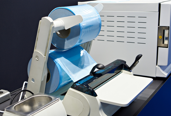
Thin film characterization can provide information about the number of layers present in a film and the thickness, composition, and structure of each layer. Thin film characterization can also be used to identify defects, inclusions, or air bubbles in a film.
A thin film is a layer of material that is nanometers to microns in thickness. Thin film coating is used by many industries, including electronics, semiconductors, medical devices, and packaging. Thin film characterization often requires a cross-section preparation. This highly specialized sample preparation is done by broad ion beam (BIB) milling, focused ion-beam (FIB) lift-out, or ultramicrotomy.
The Problem:
A multilayer film manufacturer wanted more information about their product, a multilayer film used to package a pharmaceutical product.
The Analyses:
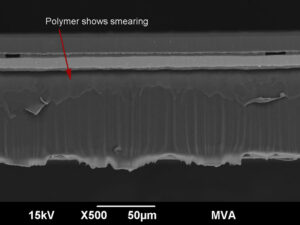
The sample was first cross sectioned using a razor blade. The image (on the right) is a scanning electron microscope (SEM) image of the cross-section. The razor blade smeared the polymer during the cutting process. This sample preparation technique was quick and appropriate for a preliminary examination, but it did not work for a complete and thorough characterization
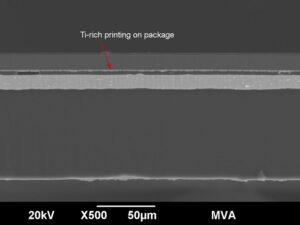
A cross-section was then prepared using a BIB instrument. The instrument bombards argon ions on a surface resulting in atoms sputtering from it. The sputtering creates a finely polished surface which is ideal for cross-section examination. Using this technique, we can easily see the different layers in this multilayer film. We can obtain the layer thickness measurements and the elemental composition of each of the layers. The thick, bright layer is made of aluminum.
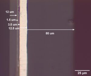
This shows a brightfield optical image of the cross-section of the multilayer polymer film. A calibrated scale was used to perform the layer thickness measurement. The lighter color layer is metallic. The three darker layers are polymers.
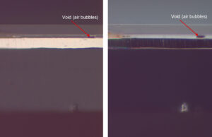
On the left is a brightfield reflected light image and on the right is a darkfield reflected light image. Both are at 500X magnification. Different illumination techniques provide different types of contrast, which can aid in seeing product defect in samples. In these images, we see there is a void or an air bubble between the layers. Layer separation is more common when there are more air bubbles.
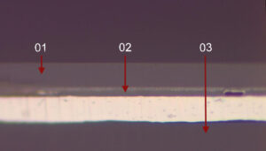
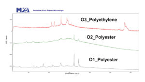
After analyzing the layer structures and measuring the layer thickness, the next step is to identify the polymer composition in the packaging material. We placed the sample in a confocal Raman microscope and analyzed the different layers with a 785 nm laser to produce some beautiful spectra. This instrument is awesome when the samples cooperate and don’t fluoresce. Out of the three polymer layers, two were polyesters and one was a polyethylene polymer. The two polyesters showed some spectral differences, meaning they also had a molecular variation. The inner layer is usually the thicker layer, and in this case it was a polyethylene polymer.
THE OUTCOME:
We were able to provide our client with comprehensive information regarding the structure and composition of his product.
Please contact us at 770-662-8509 or info@mvainc.com to learn more about our thin film characterization capability.
Our resource center archives our case studies, published articles, blogs, webinars, and image galleries. Discover ways microscopy has made a meaningful impact.

